Individual assignment #1: Orifice plate flow meter
In this exercise a standardized, axisymmetric orifice plate equipped with annular slots is to be analyzed. The flow patterns are to be monitored and compared to the computation methods defined in the Standard.
|
The sketch on Fig. 1. is based on the MSZ EN ISO 5167-1:2000 Standard. There are several criteria which apply on the dimensions marked on the figure: 50 mm ≤ D ≤ 1000 mm 0.1·D ≤ d ≤ 0.75·D and d ≥ 12.5 mm 0.005·D ≤ e ≤ 0.02·D e ≤ E ≤ 0.05·D If e ≠ E then F = 45° ± 15° 0.01·D ≤ a ≤ 0.02·D and 1 mm ≤ a ≤ 10 mm There are another conditions to meet, these are the lengths of the straight pipe sections before and after the plate. These numbers can be found in Table 1. below. |
Fig.1.: Standard orifice plate |
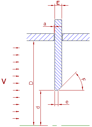

Table 1.: straight pipe sections before and after the plate
Create a CFD model of a standardized orifice plate based on the criteria above. The pipe diameter (D), the diameter of the orifice hole (d), and the inlet velocity (v) (the turbulence properties are to be set as in a fully developed flow) is to be found in the Table of Model Parameters. The temperature of the fluid at the inlet is 20 °C, the pressure at the outlet is 0 Pa. There is a hydraulic device before the pipe section which is also defined in the Table of Model Parameters. All other geometric parameters are to be arbitrarily chosen according to the Standard.
Task 1. (5 points)
Prepare three numerical meshes with different cell counts maintaining the similarity of the appropriate elements. For comparable results, decide the aspect ratio and the skewness appropriately for all meshes. Take into consideration the applicability of the Richardson extrapolation while setting the mesh count ratios.
Task 2. (4 points)
Set air as fluid. Two density models should be used for all meshes: incompressible and ideal gas. Pay attention to the appropriate density setting. The viscosity is constant, its value is to be set based on the Appendix.
Task 3. (4 points)
Perform a simulation with all meshes and fluid settings, monitoring the pressure difference on the pressure taps before and after the orifice plate. Use steady or unsteady model based on the progress of the iteration. The turbulence model is to be found in the Table of Model Parameters.
Task 4. (6 points)
Calculate the volume flow rate from the pressure difference on the orifice plate according to the Standard (the calculation method is in the Appendix). Calculate the volume flow rate from the inlet boundary conditions. Compare the results.
Task 5. (6 points)
Prepare a brief report about the aims of the analysis, including the flow patterns and the pressure distributions.
The report is to be created in PowerPoint (.PPT) format, and is to be uploaded to the personal directory.
Appendix: Calculating the flow rate on an orifice plate
|
Notation: |
|
|
Density of the fluid: |
|
|
Temperature of the fluid: |
T [K] |
|
Kinematic viscosity of the fluid: |
|
|
Diameter of the pipe: |
D [mm] |
|
Diameter of the orifice hole: |
d [mm] |
|
Diameter ratio: |
|
|
Reynolds number: |
ReD = v·D/ |
|
Measured pressure difference: |
|
|
Flow coefficient: |
|
|
Expansion coefficient: |
|
|
Volume flow rate: |
qV [m3/s] |
The volume flow rate qV can be
calculated from the pressure difference ![]() p measured on the pressure taps of the orifice plate as shown below:
p measured on the pressure taps of the orifice plate as shown below:

From this, the flow coefficient ![]() and
the expansion coefficient
and
the expansion coefficient ![]() has to
be calculated using iteration, as shown below:
has to
be calculated using iteration, as shown below:
![]()
where the value of C can be calculated as:
![]()
and the value of A is:
![]()
The viscosity for the Reynolds number can be calculated as (in case of air):
![]()
The compressibility of the fluid is taken into account using the expansion coefficient (compressibility factor):
![]()
In this task the pressure change is small, so the
expansion coefficient can be approximated as ![]() = 1.
= 1.
It is usually enough to do 2-3 iteration steps using
the equations above. For the initial value it is recommended to set the flow
coefficient to ![]() = 0.6.
= 0.6.
References:
MSZ EN ISO 5167-1:2000 Measurement of fluid flow by means of pressure differential devices